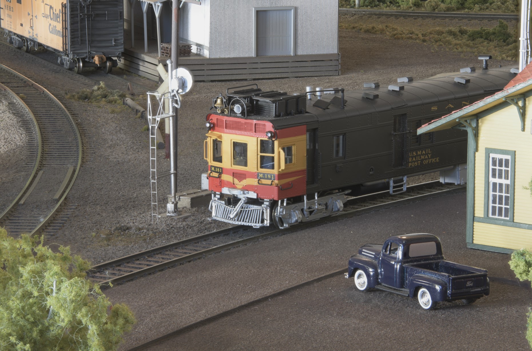
A 4-unit set of F7's exiting Shandin's industrial
(inner) track. The track layout is shown
in the drawing
below.
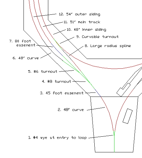
This is a drawing
of a portion of the Shandin Loop with the different elements of track
highlighted in different colors. The colors designate the following
elements:
-
Green: Turnouts and associated straight track
-
Red: Constant radius curved track except for one segment which I’ve left in black for visibility.
-
Blue: Easements or their equivalent
As I thought about
how to go about designing a loop module set, I decided early on that the
track plan would determine the physical structure of the loop, not the
other way around. I wanted to design a multi-track loop so that there
would be room for placing trains on the track, staging of trains, and
passing tracks for trains passing through the loop. The three tracks of
the loop have been more useful at setups than I ever imagined. I spaced
the loop tracks 3" apart to allow plenty of room for fingers. I added a
continuous loop to the inner siding that has been useful for speed
matching of locomotives and for testing. I’ve forgotten whose great
suggestion this was, but it wasn’t originally mine.
I plotted actual
easements using the application contained in
Dale Muir’s
web site rather than using the bent stick or other method. The
reason for this was simply that it was easier for me to draw and
manipulate the easement elements in the drawing this way. I plotted the
easements full size and then reduced them to HO scale for use in the
drawing. I plotted turnouts using the NMRA standards so that I’d be sure
to know where both switch points and frogs really were. Fortunately, the Walthers turnouts I used fit the NMRA standards
reasonably well. This isn't
always the case with all turnout manufacturers.
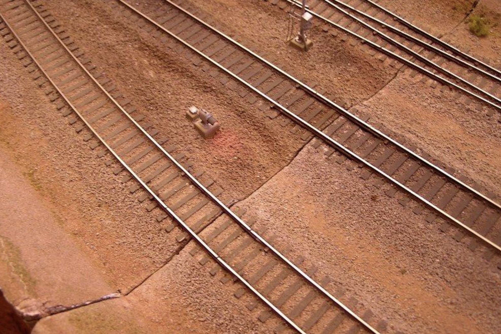
My first
significant mistake was to build just one section of the loop to see if it
would work and could be used successfully with other modules. While the
experiment was successful, the ends of the section didn’t form exactly a
45 degree angle. A related mistake which
I tried unsuccessfully to avoid was assembly of the rest of the loop
sections on a flat floor. The floor turned not to be flat after all. The
result of these problems is visible at a location where the mating point between
sections doesn’t close completely. If I were building the loop again, I
would assemble all the sections at the same time, clamped together as a
full module set, use a laser and tapered shims under module side rails
to insure that all segments were level with each other.
All turnouts were
converted to make them DCC friendly, and all electrical gaps filled with
gray ABS plastic. All frog flangeways were filled with plumbers epoxy
putty and then opened up to match the Mark IV NMRA track gauge flangeway
requirement before the putty hardened. Code 83 turnouts and flex track are Walthers and Code 70
turnouts and flex track are Shinohara.
The following
comments describe my approach to each track element called out on the
drawing above:
1. The #4 wye turnout has the same diverging track geometry
as a #8 turnout. If made to NMRA standards, the diverging switch point
has a radius of 117" and the curved closure rail a radius of 67".
Knowing this information, I decided to let the turnout act as a
substitute for a spiral easement for the adjoining 48" curve.
2. The 48" curve begins just as close to the frog of the wye
as I could accomplish. The gaps for the polarity reversing unit are just
beyond the frog of the wye to assure that only one train can cross the
reversing gaps at any one time.
3. Since the main track is modeled as the middle track of the loop,
I could have let the #8 turnout provide an easement for the end of the
48" curve. I decided, however, to insert a short easement of 45 feet to
provide a smoother flow from the 48" curve into the straight track of
the turnout (which leads to the inner siding).
4. Combined with the short 45 foot easement, the broad radius curves
of the diverging track of the turnout results in a very smooth route
into the middle track (the main line) of the loop.
5. The #6 turnout leads to the outer siding of the loop. Note that
the radius of the diverging switch point and the curved closure rail of a
#6 turnout is 43", but the effective radius is 56" since the point angle
and straight section through the frog make the effective radius larger
than the actual radius.
6. After a short straight section, the outer siding curves at a 48"
radius into the outer track which has a radius of 54". No easements were
provided.
7. After leaving the #8 turnout, the main track has an easement 80
feet long before a constant radius curve of 51".
8. The inner industrial siding has a very large radius spline of unknown radius
that joins it to the inner track of the loop.
9. The connections underneath
the rails between the ties on the curvable turnout were cut and it was adjusted so
that the radius of the diverging track was 48". The outer track then had
a larger, unknown radius.
10, 11, 12:
The loop tracks continue at a
constant radius through the loop. Bridge rails are 1" long so that they
interrupt the flow of the curve as little as possible. My experience is
that they tend to bend slightly when installed just from the pressure of
the track joiner. In any case, the visual impression is of an
uninterrupted curve through the bridge rails. The inner and outer tracks
(the sidings) of the loop are Code 70 on N-scale cork roadbed. The
middle track is Code 83 on HO-scale cork roadbed. Transitions between
the two heights are extremely gradual.
I used Walthers transition sections between code 83 and code 70
track. To insure reliable
operation, I did not superelevate the outer rail of any of the loop
track. (It’s interesting
that I have been asked more than once if the curves are superelevated.)
I used stacked card stock to achieve the very gentle vertical “S”
curve between the HO and N scale roadbed and the HO roadbed and the
subroadbed for a new siding installed after the photo above was taken.
11. Gaps separate
the loop tracks electrically from each other as required for track
detection and signaling.