I use cork for the roadbed. After the track centerline is drawn on the sub-roadbed, it’s easy to carefully align one side of the cork with its center edge along the centerline of the track when gluing it down. Butting the other half of the cork against the first carries the centerline to the top of the cork roadbed so that it can be used when laying the track. At turnouts, each half to the cork roadbed can follow its respective track centerline, and the gap between filled with pieces of cork cut to fit.
1. Use roadbed material that is resistant to expansion and contraction with humidity and temperature.
As with subroadbed, this is extremely important. Failure to do so will introduce unpredictable results with trackwork itself and the scenery that surrounds it. Ballasting and application of other scenery typically involves water-based glues which will cause problems with materials that expand when wet. Cork roadbed sealed with a coat of paint is a good solution.
2. Glue rather than nailing cork roadbed in place.
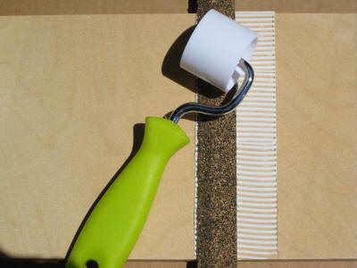
Nails are likely to create dimples and dips in cork roadbed that may show when track is installed. Use flat boards and weights to hold the roadbed down as the glue is drying. I have been happy with the appropriate Liquid Nails adhesive.
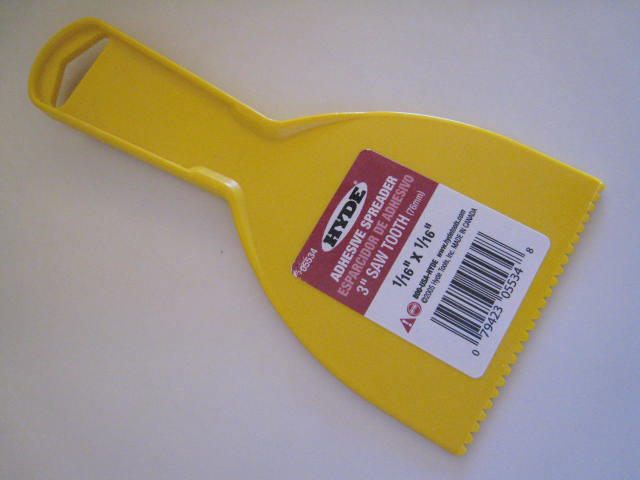
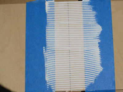
Uneven application of adhesive can result in bumps in the roadbed. Gregg Fuhriman recommends using an adhesive spreader to assure that the adhesive is applied evenly. Following his advice, I use an inexpensive spreader with 1/16” x 1/16” teeth. Keeping the teeth clean is important so that the layer of adhesive is adequate. Use this spreader when applying adhesive for track as well. One pass with the spreader will do it. Multiple passes with the spreader will reduce the amount of glue and may result in a weak glue joint.
3.
Roadbed must not introduce dips, rises and twists.
After the glue has
dried, the installed roadbed can be sanded flat with a full piece of fine
grain sandpaper wrapped the long way around a 12” long flat piece of 2” x 3”
or 2” x 4” lumber. Sand very carefully and only enough to insure that the
cork is flat and level all the way across the module. Be careful not to
create any dips, rises or twists in the roadbed. An especially troublesome
location is at the end of a module where the sanding block isn’t fully
supported by the roadbed and rounding off the end of the roadbed is a risk.
Don’t forget to remove the rough edges on the side of the cork so that the ballast
slope is smooth, but be careful not to alter the flatness of the top of the
cork roadbed when doing so.
I've recently found a great sanding block that you might consider. It's long
and very easy to use. It's called a Sand Devil and uses a sanding belt
that's used by belt sanders.
Transitions between main line track on HO
roadbed and lower level side tracks or spur tracks on N or no roadbed must
be long and extremely gradual. Very large radius vertical curves are
required. Keep in mind that 80-85 foot HO cars are about foot long. Changes
in level that are too abrupt will result in derailments, coupler mismatches
or other problems.
5.
Superelevation on curves presents special problems.
If you plan to superelevate your curves, there are a few things to keep in
mind:
It's the outer rail that's raised, not the inner
rail that's dropped. The best way to accomplish this is to shim under
the outer rail with strip wood when the track is installed. Don’t try to
build superelevation into the roadbed since it’s nearly impossible to do so
successfully. Remember that while prototypical superelevation may be as much
as 5-6”, it is most often much less than that.
Example:
Out of curiosity, I tabulated the superelevation of all the curves in the
ATSF Pasadena Subdivision in 1988 between MP 84 and MP 139. Note that some
of this was 90 MPH territory. The results suggest that modelers often overdo
superelevation.
|
Superelevation |
Frequency |
HO Equivalent |
|
None |
5 |
-- |
|
½” to
1” |
15 |
0.0115” |
|
1½” to
2” |
15 |
0.0230” |
|
2½” to
3” |
10 |
0.0344”
(~1/32”) |
|
3½” to
4” |
6 |
0.0459” |
|
4½” to
5” |
3 |
0.0574” |
|
5½” to
6” |
0 |
0.0689” (~1/16”) |
The transition from level to superelevated track must be very gradual. Superelevation introduces a twist into trackwork that will result in derailments of stiffer or longer equipment if the transition ("runoff") isn’t long and gradual. If you superelevate track, you’ll be asking the trucks of locomotives and cars to twist as they enter and leave superelevated track. Prototypical runoffs extend at least through the length of the easement (typically long) and into the straight track if necessary to maintain a gradual transition from level to superelevated track. The elevated rail is held at a constant height throughout the constant radius curve itself. The change in height of the outer rail within the runoff is raised (or lowered) lineraly across the length of the runoff.
For HO, I recommend that the length of the runoff be 4" to 6" for each scale inch of superelevation, and that the scale superelevation be limited to 4" or less. Using the 6" runoff choice and a scale 4" superelevation results in a runoff of 24". This is consistent with model trackwork experts who typically recommend a runoff equal to twice the length of the longest cars that will be operated.
Unless you’re confident of your ability to incorporate superelevation
correctly, skip it.
Broad, smooth curves and trackwork will often lead observers to think that
track is superelevated when it isn’t.
This takes careful planning but is
impossible to do after track is laid. An oversize hole makes certain that
you have room for the switch machine actuating wire.
Gregg Fuhriman’s technique may be best for
you. Drill a
large hole in the subroadbed, lay the cork right over it, and then use an
X-Acto knife or saw to make a narrow slot in the cork where the throw-rod of
the turnout will be. All this will work only if the exact location of the
turnout throw-bar has been clearly marked at its exact eventual location on
the subroadbed ahead of time during the centerline drawing phase.
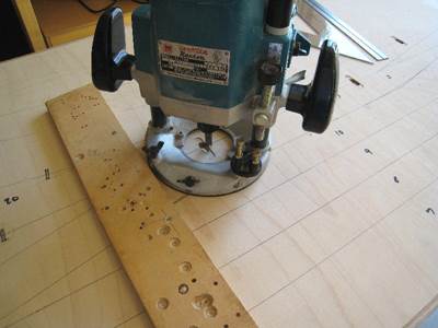
Since the construction drawings were very precise,
I was able to use a plunge router to create slots for actuating wires and clearance
space for turnout throwbars in the plywood top of Mojave Yard.
7.
Pre-drill holes for track power feeder wires only if
under-rail feeders are planned.
While I don’t recommend it, this is the
preferred method for some Free-mo modelers. I prefer to solder feeder wires
to the outer side of rails after track is installed since planning hole
locations for feeders before track is laid is difficult to do successfully.
If you plan under-rail feeders, drill holes before laying track and make
sure that they permit you to lay down the track exactly where you intend it
to be.
As I said above, I prefer to solder feeders to the outside of rails. If you can find a coyp, there’s good advice on track feeders (and other subjects as well) in Easy Model Railroad Wiring by Andy Sperandeo.
8.
Seal the roadbed before laying any track.
This will extend the life of the cork or other material and will reduce if not eliminate shifting with temperature or humidity. Sealing with paint similar to the ballast color will also help disguise any areas where ballast is missed during application or damaged during handling.
9.
Prepare for IR sensor installation.