All the effort devoted to sound module construction and the building of
great trackwork can be defeated by a failure to observe care in joining
modules together at setups. Here is a short list of things to check when
aligning and leveling modules and installing bridge rails.
Caution:
If repair or adjustment is required on a module, let the module owner know
and have him/her take the necessary action. Don't do it yourself unless you
are specifically asked to do so.
Caution:
As always, be extremely careful not to disturb details on modules as a setup
is being assembled. Take time to notice what's close by before doing
anything.
Note:
An important prerequisite for successful setup planning is being able to
provide an accurate drawing of your module. Gregg Fuhriman has provided
advice on how to accurately
measure a module.
1. Take the
time to make sure that adjoining modules are aligned vertically. Set the
height and level modules before working on any of the following checklist
items.
Nothing will work well if adjoining modules are not level with each other
(rail tops in the same plane). Care taken at this step will make the following
checks much easier. Some of us on the West Coast use a laser level to level
all modules in a setup. We use either a
track height tool
made by Prawn Designs or a white painted 1” x 2” stick held vertically with
a line drawn at the level of the laser beam.
2.
Check to make sure track on adjoining modules is aligned horizontally
(from side-to-side).
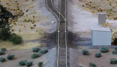
Sight down the track from one direction and the other to see that the rails
at module joints are in alignment with each other. Avoid any misalignment
that will create a jog to one side or the other. Alternatively, a straight
edge can be used along the outside of the rail, but take great care
not to dislodge the rails at module ends. Here's a good example of what to
avoid. Happily, these two offsets were corrected before operations began.
3. Check to make sure track on adjoining
modules is exactly aligned vertically (up and down).
This is a final check to make after leveling modules, especially since it's
all too common for track to rise up or fall off a bit at module ends. Use a
straight edge held against the rail tops if it is safe to do so. I use a
flat block of high quality ¾” birch plywood that is 1-1/2" wide and 5-1/2"
long that is cut very cleanly on the ends with a fine bladed saw. Sliding
this block gently back and forth along the track at a module joint will
immediately indicate which track high or low relative to the other. I make
adjustments in height until the sound made when sliding the block back and
forth is either silent or sounds the same in each direction.
4. Check to make sure that the rails
of the track on adjoining modules are level.
If the rails of the track at module ends aren't level, a twist at the bridge
rails will occur. One way to check for this is to sight across the rail
ends and the bridge rails after they are installed. Another is to use a
minature digital level. Because track at module
ends occasionally drops off to one side or the other, a module endplate
might have to be tilted one way or the other to compensate for any twist in
the track at the module end.
5. Clamp modules together tightly.
It's not unusual for modules to be bumped or jostled while setting up or
during a setup. This is especially true for multi-track modules or modules that provide an
duck-under from one side of the setup to the other. Clamping the module
joints tightly will help. If in doubt, use more than one clamp.
6. Make sure that there is room for the
track joiners.
If a module fails to provide room for track joiners underneath the rails at
module ends, it will be impossible to install bridge rails without forcing a
rise of the rails at the end of the module. This is especially important if thicker, insulating
joiners must be used for the occupancy detection and signaling system.
7. Use bridge rails and rail joiners that
match the size of the rail on the adjoining modules.
This sounds too obvious to mention, but I have replaced mis-matched bridge
rails many times. A frequent example occurs when Micro Engineering track
adjoins Walthers track on adjacent modules.
Example: At a recent setup, I found a Micro Engineering insulated rail
joiner used on Walthers track at a module end. I have no idea how it was
installed without damaging the module track. I couldn't remove it without
carving it off with a razor blade.
8. Use bridge rails of the proper length.
By this I don't mean exactly 2" long bridge rails. Rather I mean bridge
rails that leave only a small gap at either end, being neither too long nor
too short. Cut custom lengths if necessary. Smoother running will be the
result.
Throttle bus connectors will snap into the MSS sockets, but the MSS connectors will not snap into the throttle bus sockets. Installing the MSS jumpers first will avoid mis-connections and damage to MSS electrical components. Install both types of jumpers before powering the throttle bus.