I prefer to use prefabricated track since I find that it is most robust.
Others prefer tie strips with rail attached separately (e.g., Central Valley
Products), but this method may not hold up as well as prefabricated track on
modules that are transported frequently and are subject to heat and handling challenges.
Select the track you plan to use carefully. Not all brands of track are well
constructed or good looking.
1. Select the
best quality track possible.
I have made my personal evaluation of track products in
Appendix 3. Many will disagree with my opinions. Take the time
to evaluate the alternatives and select the track brand that fits your
requirements best. If at all possible, use the same brand of track
throughout your module in order to avoid different tie heights and rail
cross sections.
2. Use DCC
friendly turnouts.
If turnouts aren’t DCC friendly, either prevent shorts by making sure the
switch point rails can’t contact properly gauged wheels or convert the
turnouts so that they are DCC friendly.
3. When
building a multi-section module, join the frames together and level them
carefully so the roadbed and track can be installed as one long continuous
run across the section joints.
This helps avoid dips, humps, and misalignments at the module joints and
provides the ability to make sure that the track design is implemented as
intended. Cut the track and roadbed after the track has been installed and
the adhesive is cured.
It is very important to make sure that all segments of the module are
levelled as accurately as possible. Set the modules up and use long levels
or a laser level to insure that the roadbed on all segments is exactly on
the same plane.
Example:
The first section of Shandin Loop was built to test the construction
design. It was the first of four sections comprising a full circle. The
endplates of this first section were not oriented at exactly 45 degrees to
one another. When the other segments were built, the endplates of the other
three segments couldn’t be adjusted completely to make up for the faulty
geometry of the first segment. Additionally, I didn't level the all of the
segments as well as I might have. The result, although not noticable, are slightly discontinuous curves in the track at joints within the loop.
4. Glue, don’t
nail, track down.
Nailing track down can create dips and rises. Use lots of weights on top of
long, flat boards to make sure that track is as flat and level as possible
while the adhesive is drying. If your module top is foam, be careful not to
push overly hard in any one area to avoid "denting" the foam and creating a
low spot in the track.
5. Apply
adhesive for track so that the track centerline remains visible.
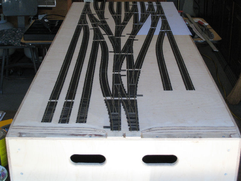
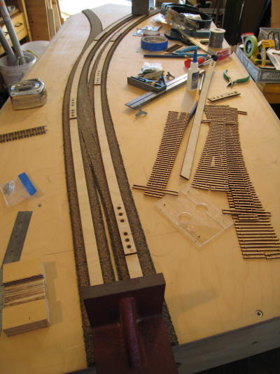
Consider "dry fitting" track before beginning permanent installation. Doing
this makes it easy to determine where you don't want adhesive. It also
provides an opportunity to make sure that all rail joints are either tight
or slightly open to allow for expansion. When doing this, I do solder short
sections or assemblies so that permanent installation is easier. As an
example, this is the "dry fit" layout of the track for Mojave Yard. I marked
the location of all rail joints (the locations with missing ties), turnout
throwbars and the outer edge of the ties so that I could mask off those
locations during application of adhesive.
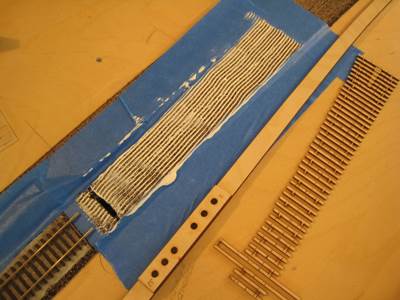
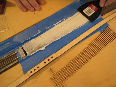
What I prefer to do is to apply two parallel lines of adhesive on each side
of the centerline. Then I
spread the adhesive with the fine-toothed adhesive spreader described in
item 2 of the handbook roadbed section. I then smooth the adhesive with a
spatula. Doing all this will keep the centerline visible and control the
amount of adhesive applied before the track is laid. Nothing is worse than
having too much adhesive push up between the ties.
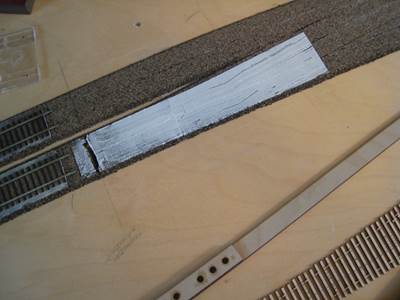
I use blue masking tape to control the spread of the adhesive and to mask
off locations where I don’t want adhesive (the location of throwbars, frogs,
rail joiners, etc.). I remove the tape before laying down the track.
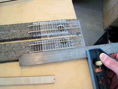
Straight track should be just that—straight—and curves should be smooth and
even. Track templates for straight track are available that are up to 18”
long. Curved track templates are available in a variety of radii from
Fast Tracks
and can be purchased for curves and easements from
Prawn Designs.
Mark the centerline of the track on the track templates and slide them back
and forth along the track, making sure that the centerline is where it
should be and that the “shape” of the track is smooth and constant.
Easements will cause a bit of a problem here, but adherence to the
centerline will provide the necessary solution. You will need to mark the
location of the beginning and the end of easements where straight and
constant radius templates can't be used.
6. Use track
templates to keep straight track straight and curved track gracefully
curved.
Using the track plan drawing, Bob Schrempp of Prawn Designs prepared track templates that included the tangents, easements, and constant radius curves for a large radius double track module. Using these tools made it easy to properly install the track exactly where it needed to be.
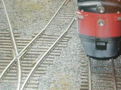
One of the most obvious flaws in trackwork is a kink where track joiners are
installed. Make rail joints and joiners very hard to locate by making
certain that there are no kinks in either straight or curved trackwork.
Example:
Take a look at the track kink in this ad for Walthers code 83 track in the
Walthers catalog of a few years ago. It also looks like there’s a vertical
kink as well.
Also notice the mismatch of rail size and railheads at the kink. Make sure
that the rail ends at each rail joiner line up so that wheel flanges won’t
catch on a rail end and derail. A transition from code 83 to code 70 rail is
provided as one of the Walters track products.
Butt-end track is being more commonly used at intra-module joints of
multi-segment modules. These are locations where it can be difficult to make
sure that the rails line up properly.
To avoid these problems, consider using “loose rail” joints when bridge
rails aren’t used. With this approach, rails are run to the edge of the
module segments but secured about ¾” back from the edge. The ¾” length at
the edge of the module is left free to wiggle back and forth just a little
on top of ties of the type used under rail joiners and bridge rails. After
the module segments are aligned at the joint, a rail joiner left on one of
the loose rails is slid across the joint, engaging the rails on both sides
of the joint. This has proven to be a great way to assure that rails are
lined up properly across the joint. At tear down, the joiner is slid back
onto one of the loose rails.
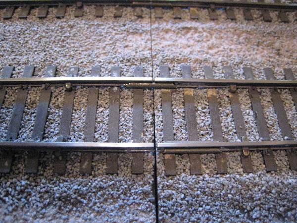
Here's a photo of a loose rail joint. In the photo, one rail joiner has been slid
across the joint and one has not. The rail must be secured at the end of the
loose rail. In this case, the rail is secured with escutcheon pins whose heads have been reshaped. Others use PCB tie
plates. In any case, the ties under the loose rails must provide room for
the sliding rail joiners. In this case, stripwood ties thinner than the flex
rail tie strip were used (notice the scarring from slips when sliding the
rail joiner that I hadn't touched up yet).
My use of escutcheon
pins is suitable only on modules with plywood subroadbed. I shape the pins
to look like an oversized spike (trim three sides, flatten the top, dress
the fourth side). I’ve always felt that this approach (pins and stripwood)
tends to look better than the PCB endplates (at least when I touch up the
stripwood). After insertion into tight pre-drilled holes, the pins are
soldered to the rail. After soldering, I add some ACC to the base of the
spike. The only risks are that too much muscle can bend the rail down (I
reduce this risk by placing a rail joiner on the free end of the rail when
inserting the pins) or that a poor soldering job can look bad, interfere
with flangeways, or melt adjoining plastic ties.
Allow for the additional thickness of track joiners under the rail. Consider
removing all ties under the joiners and sliding thinner ties into the open
area under the rails after the track is installed. Notched ties as described
by Gregg Fuhriman in item 17 (below) are another solution. I use stripwood
that is the proper width and thick enough to just slide under the joiners
without displacing the rail.
10. Decide whether rail
joints will be soldered or not.
This is a very controversial issue and one that is important for Free-mo
modelers to consider carefully. There are times that modules sit in cars and
trailers that get very hot, and some setup locations can be very warm as
well. Some advocate no soldering at all in order to provide for expansion
and contraction with heat and cold. Others argue that soldering rail joints
on curves is necessary to avoid kinks but advocate leaving unsoldered
expansion joints on straight track. Whatever you decide, joints intended to
provide for expansion and contraction must include a very small gap if they are
to be helpful at all.
11.
Install feeder wires to each separate piece of rail.
This means feeder wires (or other electrical connection) to switch point
rails, closure rails, and all other short segments of rail. The result is a lot of feeders
but elimates electrical dead spots that might cause short wheel base
locomotives (e.g., trackmobiles) or locomotives with split power pick-up (some
brass steam locomotives) to stutter or stop when passing through your trackwork. I use #22
solid copper wire bent into a short L-shape and “tipped over” to nestle into
the outside web of the rail. When soldered carefully and painted, the
feeders are hard to spot. Keep the length of #22 feeders short and patch
into heavier wire if the feeder wire is more than about 6” long.
As I mentioned previously, there’s good advice on feeders and other wiring
considerations in
Easy Model Railroad Wiring (2nd Edition)
by Andy Sperandeo.
12.
Under no circumstances, feed turnout power through the switch point
rails.
This is just plain bad practice, is unreliable, and should be avoided
absolutely.
13.
Fill all electrical gaps with plastic.
Gray Plastruct can be glued into gaps and trimmed to the profile of the
rail. The Plastruct is relatively hard to see because its color is close to
the color of nickel silver rail. This will make certain that gaps don’t
close sometime in the future.
14. Consider filling
frogs with plumbers putty.
This isn’t necessary, but it does eliminate wheel drops and provides for smoother passage of rolling stock with .088” wheel sets. Fill the frog flangeways with plumbers epoxy putty, and then open up the flangeways using a Mark IV NMRA gauge as a tool while the putty is still workable. After painting the rail, the result looks good and performs well. Note: Equipment with oversize flanges will not work with this modification.
15.
Verify that track joints are smooth and that track through turnouts
is flat and level.
While some would claim it’s a bad idea, after installation I file the rail
throughout the length of turnouts and crossings with a wide, very fine flat file. I
find that doing so eliminates uneven rail ends, plastic, and joints and levels the
rail through turnouts where the frog or other rail segments might sit too
high relative to the rest of the turnout. Following this, I polish the rail
with a very fine grade abrasive block as needed.
16.
Remove the plastic that fills the gaps on some prefabricated turnouts
and crossings.
The molded plastic often stands higher than the rails and extends into the
flangeways. This is especially true with Walthers turnouts and crossings.
Careful cutting and filing will remove the plastic and result in much
smoother operation.
17.
Use heavy wire for Tortoise switch machines.
The wire provided with Tortoise switch machines is too light for reliable
operation. While you can get away with a smaller diameter, I use wire as
heavy as 0.039” piano wire. The result is very tight fitting switch point
rails and very positive operation. You’ll have to open up the holes on the
Tortoise for the heavier wire. I don’t worry about applying too much
pressure to turnout throwbars since I always replace them with PCB
throwbars.
18.
Avoid dips and rises when securing rail at module ends.
It’s easy to cause a dip or rise when securing rail at module ends. If PCB
tie plates are used, make certain that the tie plate is shimmed so the tie
height and level of the PCB plate exactly matches the adjoining track exactly.
Whichever method is used, be certain that the rail is not pulled down or
raised up by the attachment method at rail ends.
19.
Leave room for fitter rail joiners and fitter rails at module ends.
Provide thinner ties to allow for the extra thickness of both metal and
plastic (insulating) fitter rail joiners. Make the area of thinner ties long
enough for the joiners to slide onto and off of the fixed rail and bridge
rail ends at the module ends. Remove the “tie plate” bits on PCB tie plates
and if needed carve out extra room for fitter rails on the ties that will be
under the fitter rails at the end of the module. This will insure that the
fitter rails will be free to adjust to small errors in alignment during
setups. I use stripwood filler ties. After painting, they’re hard to spot.
You can see what they look like at
http://www.pbase.com/bschrempp/image/43462875.
In this photo, you’ll also see again that I secure my rail ends with shaped
escutcheon pins soldered to the rails — an approach that’s possible only
with plywood subroadbed.
Gregg Fuhriman makes the following suggestions:
You must notch the first couple of ties under the
rail ends to clear the fitter rail joiners and prevent them from lifting the
rail ends. The best way to solve this is to use PCB tie plates designed for
use on Free-mo modules. They are designed with notches to clear the fitter
rail joiners, and provide a sturdy method of rail-end attachment. When not
using PCB tie plates, one of the following approaches is suggested:
a) (recommended) Before installing track, remove
the ties at the module end all the way back to where the fitter rail joiners
will be. After the track is installed and rail ends have been trimmed to the
1" setback, glue in "filler" ties that have been notched where the rails
would normally go. These filler ties extend from the module end all the way
back under the rail ends. Usually two notched ties under the rail ends are
needed to leave enough clearance for the fitter rail joiners. I set up my
Dremel tool on the workbench and "dado'ed" a bunch of ties to make the
notches. This is much easier
than carving the notches by hand with a hobby knife.
b) (not recommended, but might be your
only choice if your track is already down)
Install the track including ties all the way to the module
endplate. Cut back the rails the required 1" and remove. Use a hobby knife
to carefully notch ties (in place) to clear fitter rails and joiners. This
involves digging into the ties under the rail ends with the knife point.
This is a challenging task as it's very easy to accidentally tear up the
rails, etc.
20.
Make sure that roadbed, ties, tie plates and any other trackwork
structure is absolutely flush with the end plate.
Any subroadbed, roadbed or track that projects beyond the end plate will
prevent a tight connection to the next module with and may damage trackwork
on both modules.
21. Check ALL trackwork
with an NMRA Mark IV track gauge.
It’s surprising to discover how often this is overlooked. Check for gauge,
electrical and mechanical switch point rail clearances, guardrail
clearances, flangeway depths and widths, and clearance of details installed
on the track (e.g., railbars). Correct any problems that you find. While
you’re at it, check the gauge of all your locomotive and rolling stock
wheelsets as well as coupler heights. It’s surprising to find out how many
wheelsets are out of gauge.
Testing track by rolling
a box car back and forth is not an adequate test of trackwork.
22.
Make sure that nothing between or next to the rails is as high as or
higher than the tops of the rail.
Road crossings, paved areas and other scenic elements can prevent electrical
pickup, rail cleaning, cause derailments, and snag low hanging details and
coupler levers if they are higher than the rail tops between or next to the
track.
Example:
A dragging equipment detector that was higher than the rail tops was
installed between the rails. A low hanging coupler lever snagged on the
detector and instantly stopped the progress of a passenger train.
Example:
Pavement was higher than the rail tops at a road crossing. The wheels of
passing trains were lifted to the level of the roadway and derailments and
loss of power resulted.
23. Keep turnout switch
point rails, flangeways, and all moving turnout parts free of ballast and
other scenic material.
This takes time and isn’t easy! Keep the full length of the switch point
rails and the throw rod free of anything that will interfere with the free
operation of the turnout. The switch rails on Walthers turnouts are
especially long while Fast Tracks turnouts flex the closure rails without a
hinge. Both need full ability to move when the switch is thrown.
Example:
The long switch point rails of a Walthers turnout embedded in pavement were
restricted from moving from one position to the other across their full
length. The result was that a short portion of the switch rails had to bend
to accommodate the change in position of the turnout. Finally, the
attachment of the switch rails to the throw bar failed.
24. Remember to clean
paint and glue off of railheads.
While it’s obvious, it’s surprising how often this simple chore is
forgotten. Do it completely.
Make the railheads shine.
25. Clean track and wheels
regularly.
Clean track and wheels mean reliable operation. Blinking headlights are a
dead giveaway that one or the other or both need immediate attention. How
best to do this is a very controversial topic. I use the Woodland Scenics
track cleaning blocks sparaingly. I prefer the less abrasive
side and regularly wash the dirty surface off the block with and
soap and water. After using an abrasive
block, I wipe my track with an alcohol dampened cloth.
Several important words of warning when it comes to track cleaning:
Don't clean your track using materials like Goo Gone, oils or any other chemicals that will be transferred to wheelsets or other modules without the other module owners’ knowledge and permission. Ask first! The same is true of application of oils or other materials that are intended to improve power pickup that other module owners avoid.
Don’t
clean the track on someone else’s module without their knowledge and
permission. They may have detailed their trackwork in a way that you might
not notice (e.g., painted guard rails on turnouts, etc.). Ask first!
When cleaning, WATCH OUT FOR TRACKSIDE DETAILS. It’s easy to break scenic
details that took a lot of time to create and install.
26. Consider using my
bridge rail recommendations.
I performed some experiments on bridge rail installation to determine what appeared to work best. Here’s a description of what I found worked best. We are now using this scheme at most CA setups with good success.